Shaft Coupling
Introduction to Flexible Shaft Couplings:
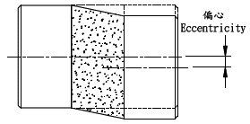
A shaft coupling is a mechanical device that connects two shafts, allowing them to rotate together and transmit safe torque. Generally, shaft couplings can be classified into two main types: flexible and rigid shaft couplings. When it is challenging to align two shafts in a straight line during power transmission or when the installation of both shafts is straightforward, flexible shaft couplings are recommended. These flexible shaft couplings absorb shocks, accommodate parallel and angular misalignment, and improve the power transmission characteristics of the system. As a result, even if there is slight deviation in shaft alignment during installation, the bearings won’t experience undue stress. Flexible shaft couplings find widespread applications in the market. On the other hand, rigid shaft couplings are unable to accommodate eccentricity or angular misalignment and rigidly connect the two shafts. Therefore, high concentricity is essential when using rigid shaft couplings.
Selection Criteria for Shaft Couplings:
When choosing a suitable shaft coupling type, consider the following factors based on mechanical characteristics and system operation:
- Torque Capacity: The shaft coupling’s torque capacity should be twice the maximum transmitted torque. For example, if the transmitted torque value is 5 N·m, select a coupling with a torque rating of 10 N·m. Steel couplings are preferable due to their torque capacity.
- Flexibility/Rigidity: Flexible shaft couplings can absorb parallel misalignment, angular misalignment, and axial displacement, while high-rigidity shaft couplings cannot. Therefore, precise shaft alignment is crucial for rigid shaft couplings.
- Environmental Conditions: Consider the material of the coupling based on factors such as acid/alkali resistance, temperature extremes, etc.
- Backlash: Evaluate whether the shaft coupling has any backlash.
- Insulation: Check if the shaft coupling provides insulation.
- Shock Resistance: Assess the shaft coupling’s ability to withstand shocks.
- Maximum Allowable Speed: Determine the maximum rotational speed the shaft coupling can handle.
- Safety Features: Look for shaft couplings that enhance machine safety.
- Bore Range Compatibility: Ensure the shaft coupling’s bore size is suitable for your application.
Shaft Coupling Connection Methods:
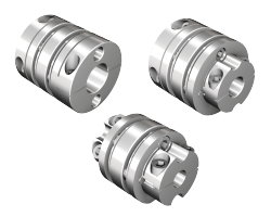
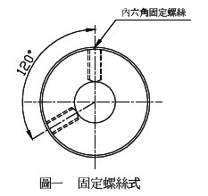
- Set Screw Type (Figure 1): This method involves fixing the shaft coupling to the shaft using four set screws positioned at 120° or 90° angles. It is easy to design, leaves screw marks on the shaft surface, and is cost-effective.
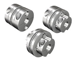
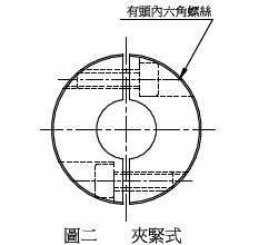
- Clamping Type (Figure 2): Clamping shaft couplings have grooves on both sides that provide elasticity. Insert two or four hex head screws on either side of the shaft. Clamping couplings are easy to disassemble, do not damage the shaft, offer better stability, and maintain a secure connection.
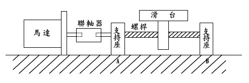
Various flexible shaft couplings come with different standard bore sizes and can be customized with keyways. High-power transmissions can use shaft couplings with machined keyways to prevent sliding and ensure compatibility with shafts larger than 32 mm in diameter. Always refer to the specifications for allowable values. During installation, pay attention to proper alignment and balancing to prevent excessive vibration, abnormal operation, or damage to motor and shaft coupling components. This will extend the mechanical system’s lifespan.
Common Terminology:
1. Parallel Misalignment: The offset between two shafts when connected.
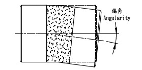
2. Angular Misalignment: The deviation between two shafts when connected.
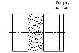
3. Axial Displacement: The movement of both shafts along their axis when connected1.